DME arcs: distance, technique and ICAO criteria
By Rory Bennett (ATPL, FI: CPL, IR, ME, UPRT, FIC) · Published 16 September 2026 · Updated 1 October 2026
Direct answer
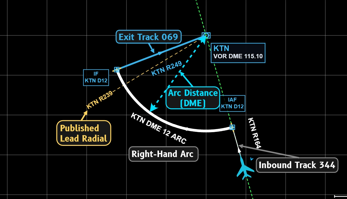
A DME arc is a curved track at a specified distance from a DME station. It is often used as part of departure, arrival, and approach procedures where a curved constant distance track is required by the procedure designer. DME means distance measuring equipment. An arc can form part of an arrival route, departure, or an initial approach. A lead radial helps the pilot start the turn onto the next track before the tracks meet. The chart gives the procedure to follow.[1][2]
Source editions: This article uses ICAO Doc 8168, Volume I, fifth edition (2006), and Volume II, sixth edition (2014). These are the editions available for this review. Later amendments are not verified here. Use the current chart and applicable operating procedures for flight.
What does DME measure?
DME measures slant range. This is the direct distance between the DME signal source and the aircraft antenna. It is not the horizontal distance across the ground.[3] For when GNSS may replace a DME on the UK IR skills test, read RNAV substitution in the IR skills test.
For example, a 12 DME arc uses a specified DME distance of 12 nautical miles (NM). The distance refers to the DME station named on the chart. The arc changes the aircraft track while the specified distance stays constant.[1][3]The arc will have a published distance, reference DME station and direction.
How do you prepare for the arc?
Read the arc as part of the complete procedure. Use this study checklist with the chart. It summarises the items to find. [1][2]
- Find the distance reference and direction. Find the DME station identifier and the specified arc distance and direction.
- Find the entry. Find the published entry fix or track. Consider direction of first turn to enter, if entering from outside, this will be opposite to arc direction!
- Find the limits. Read the published altitudes and any speed limits, usually determined by QDM, QDR, Radial as you progress around the arc.
- Find the exit. Find the next track and any lead radial. Consider setting the CRS or OBS to this to aid situational awareness.
The cited PANS-OPS sections describe arc design and lead radials. They do not prescribe a fixed 80° or 100° entry turn, or a groundspeed/100 entry formula.[1][2]
How do you follow the arc?
Follow the published arc distance and direction. Monitor the DME distance as the aircraft track changes. An RMI or RBI is often used for situational awareness and to help control whether distance increases or decreases by placing the QDM above or below the wingtip. Use the published fixes and a CRS set to the exit track to check progress towards the exit.[1][2]
A series of small heading changes is a common flying technique. This involves flying several straight segments, often of 10 degree QDM changes at a time, followed by a 20 degree turn, allowing small increases and decreases to the DME distance. The cited sections do not require a specific heading increment. They also do not prohibit a continuous turn.[1][2]
How does wind affect the arc?
Wind changes the relation between heading and track. As the track changes around the arc, the required wind correction also changes, making long arcs in strong winds particularly tricky. Each turn will require a different wind correction. To start with, it helps to brief yourself before each turn whether the wind will be pushing you into or out of the arc, then adjust the next heading by single drift out of or into the arc accordingly. Another way to think about it, if using an RBI or RMI, is to adjust the datum further up or down, up if being blown out of the arc, down if being blown in.
What is a lead radial?
A lead radial, QDM or QDR gives a reference before the arc joins the next track. It helps the pilot allow for the distance needed during the turn. It is different from the radial or track that the aircraft must intercept.[1][2]
In the cited initial approach criteria, an intersection angle above 70° requires a lead radial. That radial must provide at least 2 NM of lead. The Category H value is 1 NM.[1]This is a design minimum for the chart. It is not a flight technique. The lead you need in flight depends on your turn radius, and your turn radius changes with groundspeed.[2]
Volume I states that lead radials serve aircraft without area navigation (RNAV) equipment. They do not restrict turn anticipation by a flight management system (FMS). This statement does not, by itself, approve equipment substitution or use of a different procedure.[4]
What are the ICAO design values?
The values below come from Volume II, sixth edition (2014). They apply to different procedure segments. They are design criteria, not aircraft control instructions.
| Item | Initial approach arc | Arrival route arc |
|---|---|---|
| Minimum radius | 7 NM; Category H: 5 NM[1] | 10 NM[2] |
| Intersection with the next track | Should not exceed 120°[1] | Should not exceed 120°[2] |
| Lead when the angle exceeds 70° | At least 2 NM; Category H: 1 NM[1] | At least d = r × tan(α / 2)[2] |
In the arrival formula, r is the aircraft turn radius. It is not the DME arc radius. α is the turn angle. The calculated lead distance d uses the same units as r.[2]
For a 90° turn, tan(45°) = 1. Thus, d = r. If the design turn radius is 1 NM, the calculated lead is 1 NM. This is a calculation example, not a turn instruction for a published arc.[2]
What must you find on the chart?
Find the DME station, arc distance, entry, direction, and next track. Then find the altitude, speed limits, and any lead radial. A DME arc can end at or before the intermediate fix on an initial approach.[1]
The intermediate fix marks the start of the intermediate approach segment.[6]Do not assume that the arc connects directly to the final approach. Read each segment in sequence.
Example: read a 10 DME arc
This is an invented study example. The chart specifies a clockwise arc at 10 DME from station ABC. The arc then joins a straight track. The chart also shows a lead radial.
| Chart item | Meaning |
|---|---|
| ABC DME | Use ABC as the distance reference. |
| 10 DME | The specified slant range is 10 NM. |
| Clockwise arc | Follow the arc clockwise around ABC. |
| Lead radial | Use this reference to plan the transition onto the next track. |
| Next track | Establish the published track after the transition. |
A reading of 10.4 DME is 0.4 NM greater than the specified distance. A reading of 9.6 DME is 0.4 NM less. Neither reading, by itself, tells you the permitted tracking error.
Open the DME Arc Trainer. Read the generated exercise before flight. Identify its station, distance, direction, and exit. After the exercise, compare the recorded track with the assigned arc. The trainer score is feedback for that exercise.
Is DME accuracy a flight tolerance?
No. Volume II gives a DME accuracy value for procedure design: ±(0.25 NM + 1.25% of the distance to the antenna).[5]
For related study, read how to track a VOR radial. See instrument procedures for more approach topics.
Common mistakes
- Using distance from the wrong station. Use the DME station named for the arc. Do not assume that the distance is from the runway.
- Over-relying on bearing information. Remember, the DME is the master instrument here, the relative bearing is only used to help control whether you are increasing or decreasing DME distance on a given heading.
- Trying to fly a perfect arc with many short legs. The more legs you fly, the higher your workload and greater the threat of missing stepdowns on the procedure. 10-20 degrees of turn at a time is normally sufficient to remain within a suitable distance of the arc.
- Not accounting for changing relative wind around the arc. Remember, the effect of wind will be different on each leg. Max Drift will remain roughly the same, but the drift on each leg will vary, consider primarily whether the wind is blowing you into or away from the arc and adjust heading accordingly.
- Missing the exit radial, QDM or QDR. If you have an OBS CDI or HSI, set the CRS to the exit track and display and RMI if available, you will be able to monitor your progress around the arc by observing the difference between the RMI and exit track.
Practise this in the simulator
Use the simulator to practise this procedure. You can change the wind and monitor the instruments in your browser.
7-day free trial, no card required. Includes Just Fly, the Intercept Trainer and the Hold Visualiser. Reverts to the free tier when it ends; you are never charged automatically.
Check your understanding
Read each question. Decide on your answer. Then select Show answer to check it.
Show answer
Show answer
Show answer
Frequently asked questions
What is a DME arc?
A DME arc is a curved track at a specified distance from a DME station. It can form part of an arrival route or an initial approach. DME measures slant range.
What is the minimum radius of a DME arc?
The cited PANS-OPS Volume II edition gives 7 NM for an initial approach arc, or 5 NM for Category H. It gives 10 NM for an arrival route arc. These are procedure design values.
Does ICAO require the turn 10, twist 10 technique?
The cited DME arc sections do not prescribe that technique or another fixed heading increment. They describe procedure design. Use the flying technique taught for your aircraft and instruments.
What does a lead radial do?
A lead radial helps the pilot start the transition before the arc meets the next track. It is different from the track to intercept. Follow the chart and applicable operating procedure.
Do lead radials restrict FMS turn anticipation?
Volume I, paragraph 1.4.2, states that lead radials do not restrict FMS turn anticipation. This statement does not, by itself, approve equipment substitution or a different procedure.
Is DME accuracy an allowed error from the arc?
No. The cited accuracy value is a procedure design input. It does not set a pilot tracking limit. A trainer score also does not establish an ICAO flight tolerance.
Sources
- ICAO Doc 8168 (PANS-OPS), Volume II, sixth edition (2014). Part I, Section 4, Chapter 3, paragraph 3.3.2: DME arcs in the initial approach.
- ICAO Doc 8168 (PANS-OPS), Volume II, sixth edition (2014). Part I, Section 4, Chapter 2, paragraph 2.1.1.10: arrival route DME arcs and lead distance.
- ICAO Doc 8168 (PANS-OPS), Volume I, fifth edition (2006). Part I, Section 1, Chapter 1: definition of DME distance.
- ICAO Doc 8168 (PANS-OPS), Volume I, fifth edition (2006). Part I, Section 2, Chapter 1, paragraph 1.4.2: lead radials and FMS turn anticipation.
- ICAO Doc 8168 (PANS-OPS), Volume II, sixth edition (2014). Part I, Section 2, Chapter 2, paragraph 2.4.4: DME accuracy for procedure design.
- ICAO Doc 8168 (PANS-OPS), Volume II, sixth edition (2014). Part I, Section 1, Chapter 1: definition of intermediate fix.
Related articles
This article is for study. Follow the instructions from your qualified flight instructor. Use current charts, procedures, and the regulations from your aviation authority.
© 2026 RHBA Radio Navigator. All rights reserved.